A multimeter is invaluable for the DIY troubleshooting of electrical problems around the house. You can use it to identify faulty wiring, check if electrical sockets have power, and test batteries. My electrical engineer brother-in-law, Ryan Davis, recently showed me how to use one. Here’s a write-up of what I learned. Maybe you’ll find it handy.
What Does a Multimeter Measure?
A multimeter measures three electrical properties:
- Voltage (Volts): The electrical potential difference that pushes electrons through a circuit. Measure voltage to check battery charge or verify power in outlets.
- Current (Amps): The flow of electrical charge through a conductor, indicating how much electricity is moving through a circuit. Measure current to verify that circuits or devices are drawing the correct amount of electricity.
- Resistance (Ohms): How much a material opposes electrical flow. Higher resistance means less electricity flow. Measure resistance to check component continuity, verifying that a wire or fuse isn’t broken.
Basic Multimeter Components
Multimeters come in analog and digital forms. One of the nice features of digital multimeters is that they’re auto-ranging, meaning the multimeter automatically selects the correct measurement range for the quantity you’re testing — voltage, current, or resistance — so you don’t have to manually dial in an expected value range. That makes digital multimeters easier for beginners to use.
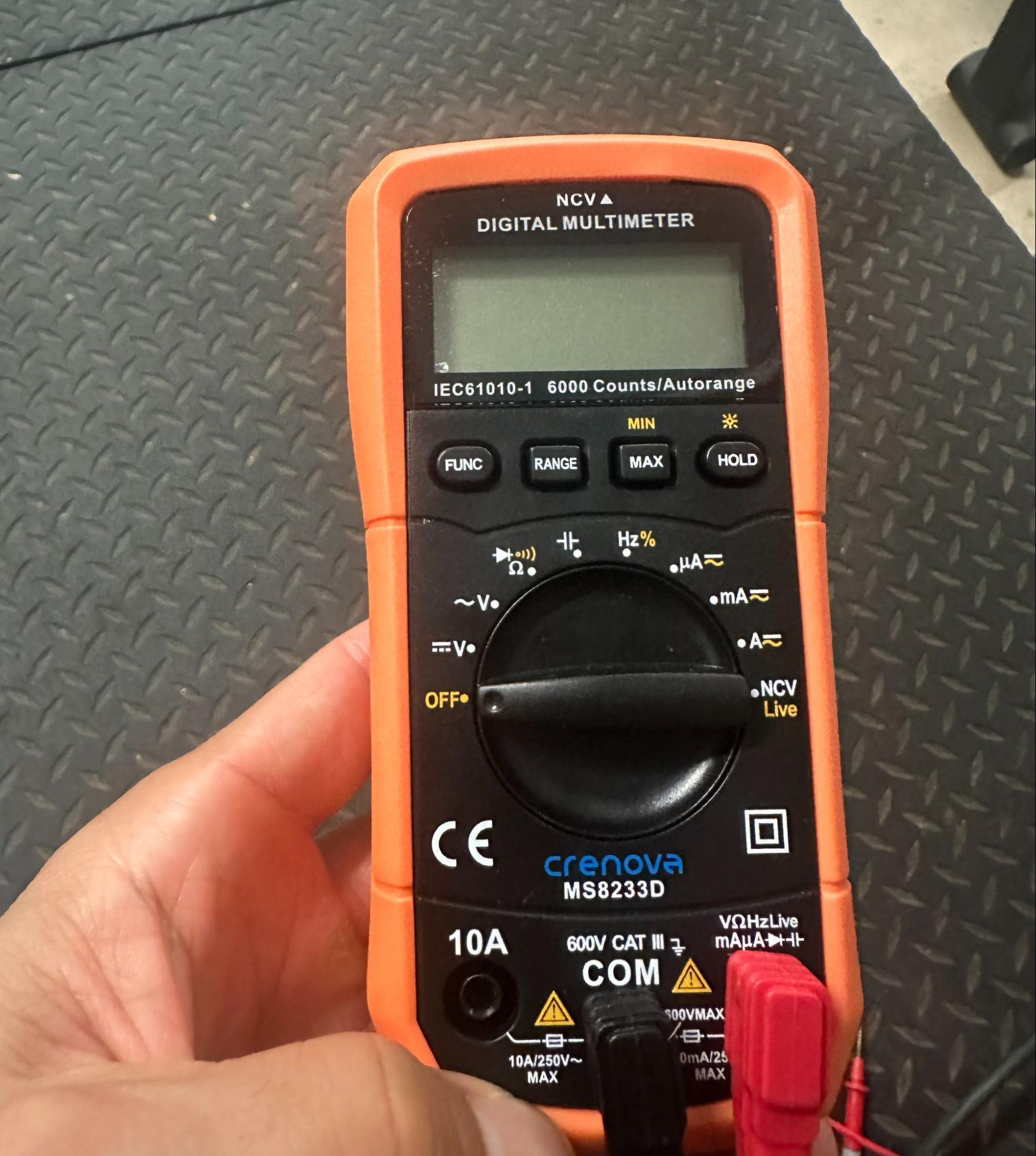
The main components of a multimeter (whether digital or analog) include:
- Display: Shows the measured value.
- Dial: Lets you select what to measure (voltage, current, resistance).
- Ports: COM (black) and two red ports: one for voltage, resistance, and milliamp/μA measurements, and one for high current (up to 10A). Most pro multimeters separate the ports for measuring voltage/resistance and milliamp/μA. There will be a port you use when you’re measuring voltage and resistance measurements. Never plug into the 10A jack unless you’re measuring large currents.
- Probes: Black (negative) and red (positive) wires to connect to test points.
Real-World Applications
Testing Batteries (Voltage)
You can use a multimeter to test if your batteries still have juice. Here’s how to do it:
Plug the black probe into “COM” and red probe into the milliamp/μA port.
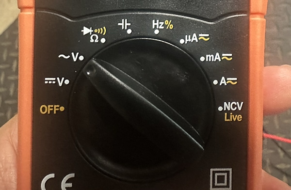
Turn the dial to AC voltage (~ V).
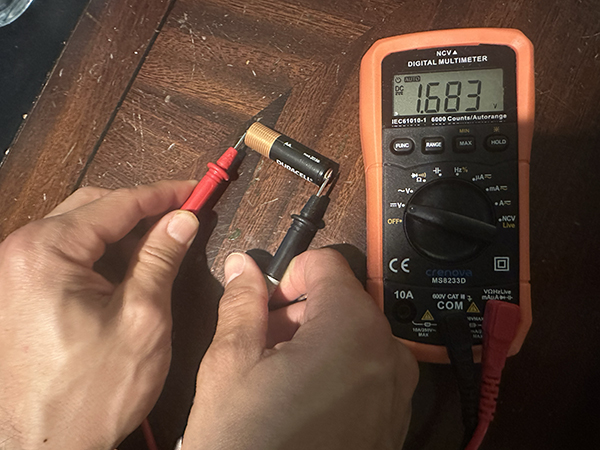
Touch red probe to battery’s positive terminal, black to negative.
Read the display — AA/AAA should be around 1.5V, 9V around 9V, car batteries 12.6V when charged.
Testing for Parasitic Draw (Current)
A few years ago, my car wouldn’t start in the mornings. Once I jumped the battery, it was fine. The battery was good. But then a few days later, the car wouldn’t start again. I made sure I wasn’t leaving dome lights on or anything.
I ended up taking it to a mechanic, and he used a multimeter to discover a parasitic draw from a wireless phone adapter plugged into the cigarette lighter. Here’s how I could have used my multimeter to diagnose this on my own:
1. Set Up Your Meter
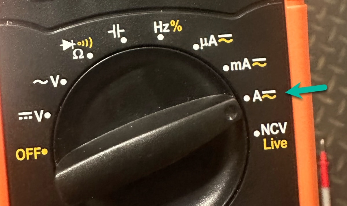
- Turn the dial to DC Amps (A⎓ or mA⎓).
- Plug the black lead into COM.
- Plug the red lead into the mA jack.
2. Break the Circuit at the Negative Terminal
Use a wrench to loosen and remove the negative battery cable from the battery post.
3. Connect the Meter in Series
You’re going to place the meter in series, which means you’re connecting it directly into the path of the electrical current. Instead of electricity flowing directly from the battery to the cable, it now flows through the meter first, then continues to the cable. Because the meter and cable form a single continuous path (like links in a chain), they’re said to be connected “in series.” This setup lets the meter measure all the electricity moving through that pathway.
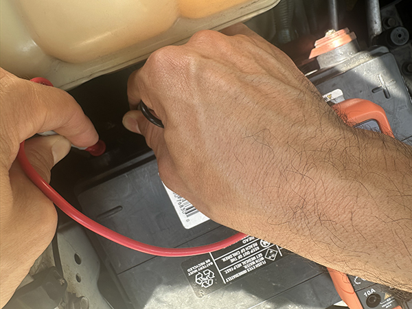
It’s hard to see what I’m doing in this pic, but it’s this:
- Touch the black probe to the negative battery post.
- Touch the red probe to the loose battery cable.
- You’ve now inserted the multimeter in series and the battery current is flowing through your meter.
4. Read the Display
- A normal reading is typically 20–80 milliamps (0.02–0.08A).
- Anything above 100mA (0.1A) is excessive and warrants investigation.
5. Track the Culprit
If the meter reads above 100mA:
- Have another person start pulling fuses one at a time from the fuse box.
- Watch the current draw after each one.
- When the draw drops significantly, you’ve found the circuit responsible. From there, trace what’s connected to it.
Testing Extension Cords (Resistance/Continuity)
Extension cords take a beating. Over time, the insulation can crack, wires can loosen, and corrosion can creep into the connections.
A damaged extension cord is a fire or shock waiting to happen. Fortunately, your multimeter makes it easy to test cords and catch problems before they become dangerous.
Step 1: Check for Continuity and Shorts
Start with the cord completely unplugged.
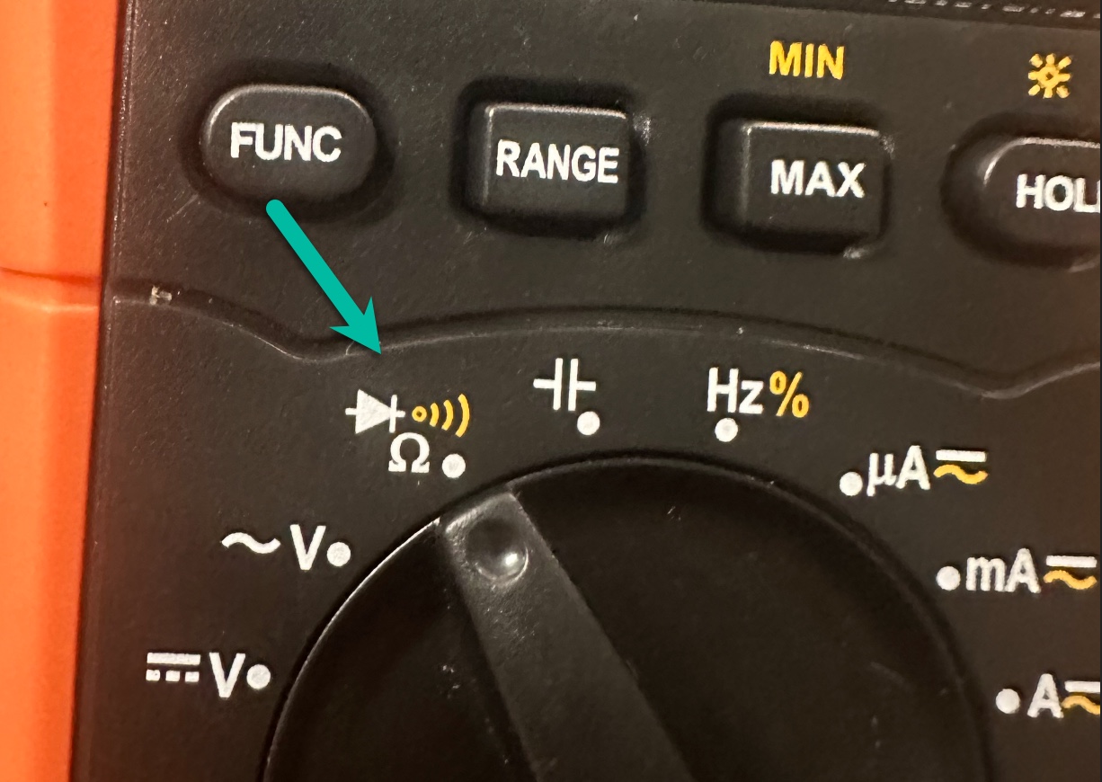
Set your multimeter to resistance (Ω) or continuity mode. Plug the red probe into the voltage/resistance port.
To test each wire:
Ground:
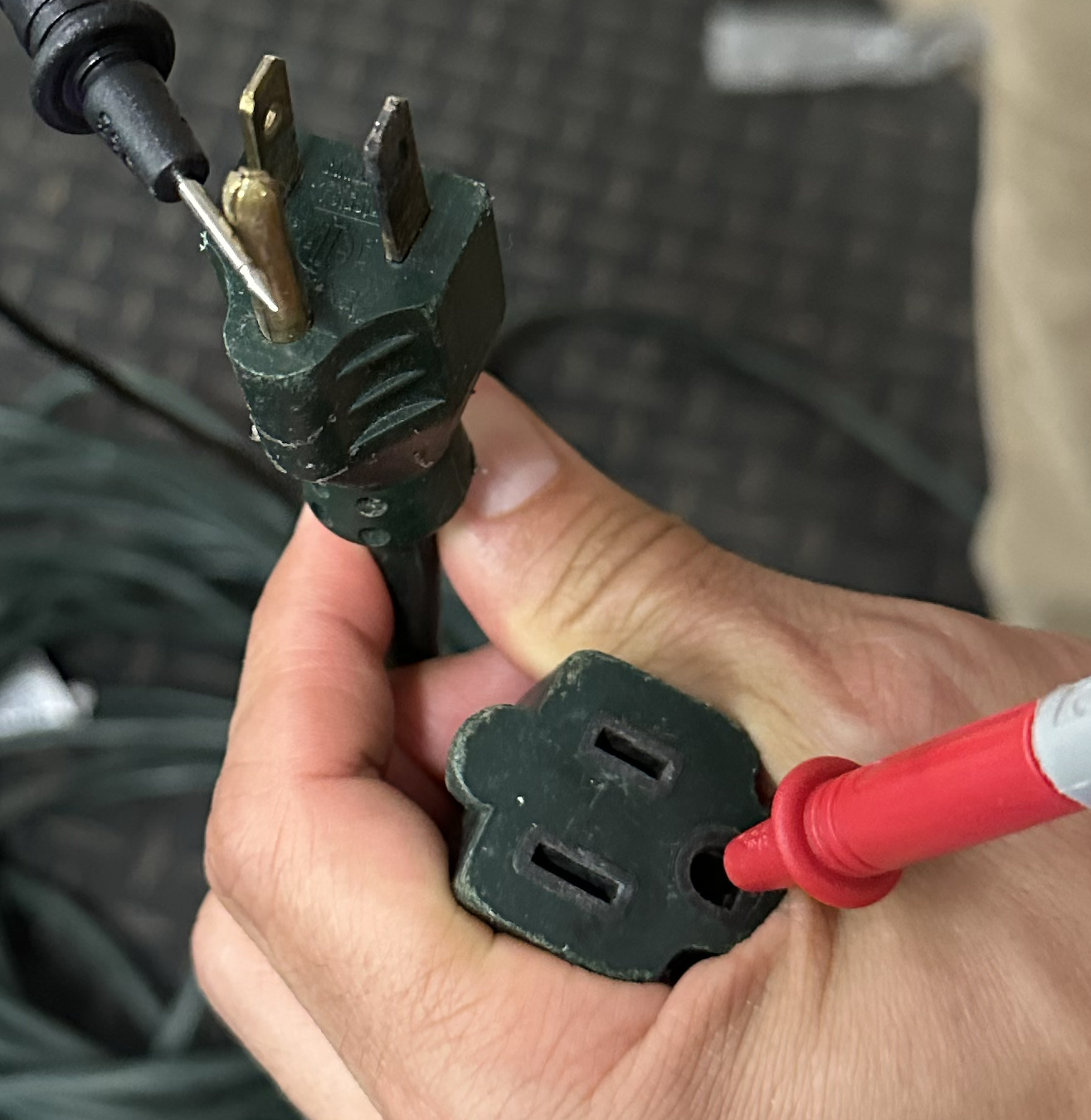
- Insert the red probe into the round ground hole on the female (plug-in) end.
- Touch the black probe to the round ground prong on the male (wall plug) end.
- Expect a reading under a few ohms depending on cord length and gauge. Anything over ~5 ohms could indicate corrosion or a partial break.
Now check for shorts:
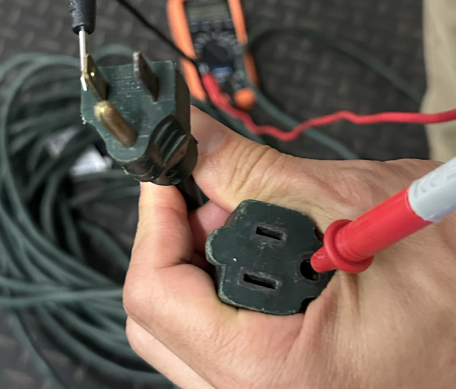
- Keep the red probe in the ground hole and touch the black probe to each flat prong on the male end.
- Your multimeter should display “O.L.” or infinity, indicating no connection. If you get a low reading, the cord has a short and should be tossed.
Hot and Neutral Slots:
Repeat the same procedure for the short (hot) slot and long (neutral) slot:
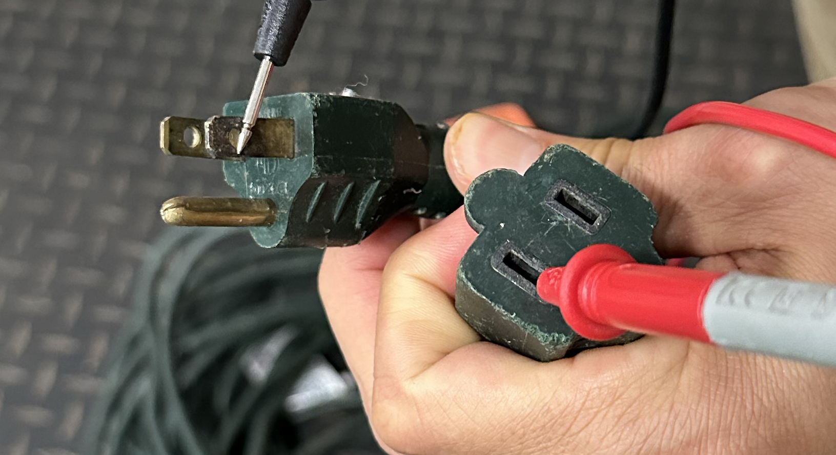
- Match each slot to its corresponding prong and test for continuity (0.8 ohms or less).
- Cross-test against the other prongs for “O.L.” readings to confirm there are no shorts between wires.
If any test shows continuity between circuits that shouldn’t be connected, that cord goes in the trash. It’s not worth trying to repair.
Step 2: Test for Live Voltage
Once you’ve confirmed the cord isn’t damaged, you can check that it’s delivering voltage properly.
Plug the cord into a live wall outlet.
Set your multimeter to AC voltage (VAC).
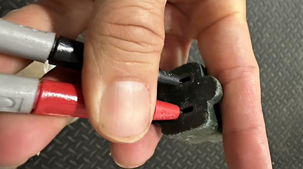
Insert the probes into the two female holes of the cord. You should get around 120 volts.
Move one of the probes to the ground hole (it’s round). You should again see ~120 volts.
These readings confirm the cord is carrying voltage properly and safely.
There you go. How to use a multimeter. Whether you’re checking batteries, hunting down mysterious electrical problems in your vehicle, or making sure your extension cords aren’t fire hazards waiting to happen, this simple tool can save you time, money, and headaches.